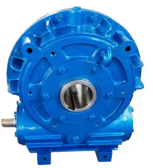
How to ensure the relative position accuracy between the motor and the gearbox when installing SCWS80-50-2 worm gear reducer
To ensure the relative positional accuracy between the motor and SCWS80-50-2 reducer, the core is to control the error throughout the entire process from base leveling, shaft alignment to component connection through "benchmark alignment, step-by-step fixation, and precise measurement", ultimately achieving the three key parameters of levelness, coaxiality, and spacing.
1、 Preparation in advance: Setting benchmarks, selecting tools, eliminating basic errors
This is a prerequisite for ensuring positional accuracy and avoiding difficulties in subsequent adjustments due to initial condition deviations.
Benchmark surface treatment and leveling
Thoroughly clean the installation base of the motor and reducer, remove oil stains, rust, and protruding debris, and use a flatness ruler to check the flatness of the base, with an error of ≤ 0.05mm/m; If the base is uneven, use a precision copper gasket (with a thickness accuracy of 0.01mm) to level it below the base, ensuring that the installation surface is at the same level.
Preliminarily fix the reducer on the base, use a level with an accuracy of 0.1mm/m, and press it tightly against the flat surface of the reducer housing and the flange surface of the input shaft. Adjust the gasket at the anchor bolt to make the levelness error of the reducer ≤ 0.1mm/m, tighten the anchor bolt (torque according to the instructions, usually 20-30N · m), and fix the benchmark position of the reducer.

Tool selection and calibration
Digital dial gauge (accuracy 0.001mm, equipped with magnetic gauge holder), used to measure the coaxiality of the shaft system, reducing reading errors compared to ordinary dial gauges.
Calipers (accuracy 0.02mm) are used to measure the distance between motors and reducers, as well as the clearance between coupling end faces.
Torque wrench, ensure that the bolts are tightened to the specified torque to avoid position deviation caused by excessive looseness or tightness.
High precision measuring tools must be used to avoid visual judgment. Suggested preparation:
2、 Core steps: Control relative position accuracy in three steps
Taking the conventional scenario of "connecting the motor and reducer through a coupling" as an example, follow the step-by-step operation of "coarse positioning → fine alignment → fixed review" to control the error throughout the process.
Step 1: Rough positioning - Determine the preliminary position of the motor
Referring to the center height of the input shaft of SCWS80-50-2 reducer (according to the model parameters, the center height usually matches the "80" center distance, about 80mm), choose a motor with the same center height to avoid shaft tilting caused by differences in center height.
Place the motor on the base, move the motor to align the axis of the motor shaft with the input shaft of the reducer (with no obvious deviation observed by the naked eye), and ensure that the distance between the motor and the reducer meets the design requirements (usually reserved 10-20mm operating space for subsequent coupling installation), completing rough positioning.

