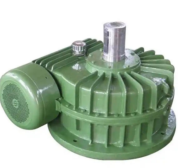
How to perform shaft connection and centering when installing TPS315-40 planar enveloping toroidal worm gear reducer
TPS315-40 belongs to a large planar enveloping toroidal worm gear reducer, and the alignment accuracy of the shaft system directly affects its operational stability and service life. It is necessary to make preliminary preparations, then select appropriate methods for precision adjustment according to the accuracy requirements, and finally verify the alignment effect. The specific operation is as follows:
1. Preparation before the match
Basic and component inspection: First, confirm that the foundation bolts of the reducer have been pre tightened and that there are no "soft feet" on the base (poor contact between the base and the bottom plate). Use a feeler gauge to insert into the gap of the base for inspection. If there is a gap, add a gasket to fill it. At the same time, clean the oil stains and burrs on the coupling and shaft end, check that the coupling is not deformed, the elastic components are not damaged, and the radial runout of the shaft should be ≤ 0.05mm. If the shaft is bent, it needs to be corrected first.
Coarse alignment base: Use a ruler to fit the circumference of the coupling, preliminarily align the motor shaft with the input shaft of the reducer, the output shaft of the reducer with the load shaft, and ensure that the flange edges of the two shafts are roughly flush. Use a feeler gauge to measure the clearance in four directions around the circumference of the coupling: 0 °, 90 °, 180 °, and 270 °, ensuring that the clearance difference is ≤ 0.1mm to reduce the difficulty of adjustment for precise alignment.
Tool preparation: Prepare dial gauges, magnetic gauge holders, feeler gauges, thin steel washers of different thicknesses, etc. for ordinary precision scenarios; When high precision is required, prepare a laser alignment instrument and adjust tools such as wrenches.
2. Accurate centering operation
Dual meter measurement method (commonly used mainstream method): This method is suitable for most industrial scenarios and can meet the conventional accuracy requirements of TPS315-40. First, fix two dial gauges on the reference side coupling. One gauge head is pressed against the outer circle of the coupling on the other side to measure the radial deviation, and the other gauge head is pressed against the end face of the coupling to measure the angular deviation. Then manually rotate the two axes synchronously once, and record the radial and axial readings at positions 0 °, 90 °, 180 °, and 270 ° in sequence. When returning to the initial position, the readings should be consistent with the original values. If the radial deviation exceeds the standard, adjust it by adding or removing shims to the motor or load equipment base; If the angular deviation exceeds the standard, adjust the gasket slightly on one side and repeat the measurement until the radial deviation is ≤ 0.05mm and the angular deviation is ≤ 0.02mm/m.
Laser centering method (efficient and high-precision method): suitable for centering operations on high-precision or large equipment. Fix the laser emitter and receiver on the shafts on both sides of the coupling, and rotate the shaft to positions such as 0 °, 90 °, 180 °, 270 ° according to the instrument prompts to collect data. The instrument will display the radial and angular deviation values and adjust the direction in real time. Afterwards, by using hydraulic fine-tuning devices or adjusting bolt moving equipment, combined with adding or removing gaskets, gradually correct according to instrument prompts until the deviation is ≤ 0.02mm. This method can significantly reduce the difficulty of aligning large reducers.
Gauge assisted method (simplified review method): can be used for secondary review after centering. Take 4-6 measuring points evenly on the end face and outer circle of the coupling, and use a feeler gauge to measure the clearance one by one. If the radial clearance difference between each point is ≤ 0.1mm and the axial clearance difference is ≤ 0.1mm/m, it indicates that the alignment state is stable. This method can also be used for rapid alignment in low precision scenarios.