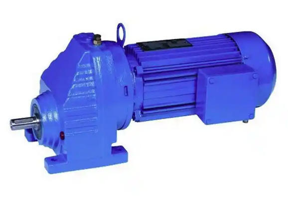
How to monitor the axial movement of the gear shaft of RX97-4.5-11KW-4P reducer
Monitoring the axial displacement of the gear shaft of the RX97-4.5-11KW-4P reducer involves a combination of "static measurement" and "dynamic monitoring" to accurately capture the axial displacement of the shaft. The commonly used tools are dial gauges or micrometers, and the operation should follow the principle of "fixed reference, vertical measurement".
1. Static measurement (stop state, precise measurement of gap)
Static measurement is suitable for daily maintenance or suspected movement, and directly measuring the maximum axial movement of the shaft is the most basic and accurate method.
Preparation tools: dial gauge (accuracy 0.01mm), magnetic gauge holder, wrench, cleaning cloth.

Operation steps:
Stop the machine and cut off the power supply, wait for the reducer to completely cool down (to avoid thermal expansion and contraction affecting measurement accuracy), and clean the oil and impurities at the end of the gear shaft (output shaft or input shaft).
Fix the magnetic gauge holder on the flat surface of the gearbox housing (ensure that the gauge holder is not shaking, as a measurement reference), adjust the dial gauge head so that it is vertically pressed against the center position of the shaft end face, and control the compression of the gauge head at 1-2mm (ensure sufficient measurement stroke).
Gently push the gear shaft back and forth (along the axial direction) with your hand, and observe the maximum swing range of the dial indicator pointer. This value is the static axial displacement.
Repeat the measurement three times and take the average as the final result. If the value exceeds 0.15mm (according to the precision level standard), further investigation of the cause is required.
2. Dynamic monitoring (running status, real-time detection of anomalies)
Dynamic monitoring is suitable for equipment that operates for a long time, and can capture instantaneous movements during operation (such as movements caused by load changes) to avoid potential issues that may be missed in static measurements.
Preparation tools: axial displacement sensor (such as eddy current sensor, accuracy 0.001mm), data acquisition instrument, bracket.
Operation steps:
Install a displacement sensor bracket at a suitable position at the end of the gearbox gear shaft (non stress side), ensuring that the sensor probe is parallel to the shaft end face, with a spacing controlled within the sensor range (usually 2-5mm), and avoiding irregular structures such as keyways and chamfers on the shaft.
Connect the sensor and data acquisition device, power on and preheat for 30 minutes, calibrate the zero point of the sensor (set the displacement when the axis is in the middle position to 0).
Start the reducer and run it for 30 minutes under two working conditions: no load and rated load (corresponding to 11KW load). Record the displacement data in real time and observe whether the data curve is stable.
If the displacement value fluctuates by more than 0.05mm during operation, or the peak value exceeds 0.15mm, it indicates the presence of dynamic movement, and the machine needs to be stopped to check whether the bearings and positioning components have failed.

