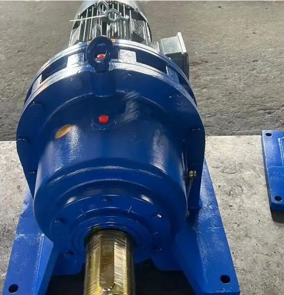
How to measure the meshing clearance of the cycloidal gear of BWD18-59-1.1KW reducer
To measure the meshing clearance of the cycloidal gear of the BWD18-59-1.1KW reducer, a combination of "static plug gauge measurement+dynamic tactile verification" is required. The core is to accurately locate the measurement point and eliminate interference factors. The specific steps are as follows:
1、 Preparation before measurement
Disassembly and Cleaning
Disassemble the reducer, remove the cycloidal gear assembly and needle ring gear, thoroughly clean the oil stains, iron filings, and wear impurities on the tooth surface and needle teeth to avoid impurities affecting measurement accuracy.
Attention: If not disassembled for measurement, it is necessary to ensure that there are no foreign objects inside the reducer and that the cycloidal gear is in a free state (non force meshing).
Tool Preparation

Feeler gauge: measuring range of 0.02-0.5mm (recommended to include commonly used specifications such as 0.02, 0.05, 0.1, 0.2mm, etc.), ensuring that the blades are flat and free of deformation.
Marking pen: used to mark measurement points to avoid duplication or omission.
Copper rod/rubber hammer: Used when slightly adjusting the position of the cycloidal gear to prevent damage to the tooth surface.
2、 Static plug gauge measurement (core steps)
Positioning measurement points
Align the cycloid gear with the needle gear ring according to the assembly position (the cycloid gear is in mesh but not under external pressure), and uniformly select 4-6 measuring points along the circumference of the needle gear ring (such as 0 °, 60 °, 120 °, 180 °, 240 °, 300 °) to ensure coverage of different meshing positions.
Insert a feeler gauge for measurement
For each measurement point, insert the feeler gauge blade vertically into the gap (radial gap) between the top of the cycloid gear and the outer circle of the needle gear, gently pull the feeler gauge, and feel a slight resistance without any jamming. The thickness of the blade is the gap value at that point.
If a single blade cannot be matched, multiple feeler gauges can be combined (such as 0.05+0.03mm), but the total thickness needs to be accurately read to avoid deformation of the tooth surface caused by excessive blade stacking.
Recording and Calculation
Record the clearance values at each point, calculate the average value (normal range reference 0.05-0.2mm, specific subject to the manufacturer's manual), and pay attention to the difference between the maximum and minimum clearances. If it exceeds 0.1mm, it indicates uneven clearance and needs to be checked for wear/misalignment of the cycloidal gear or needle teeth.
3、 Dynamic auxiliary verification
Manual rotation inspection
After measurement, manually rotate the cycloidal gear (or drive it through the input shaft) to feel whether the resistance during the meshing process is uniform. If there is obvious jamming or loosening at a certain position, it indicates that the gap in that area is abnormal and needs to be remeasured and marked.
Observation of meshing marks
If conditions permit, a thin layer of red lead oil can be applied to the cycloidal gear tooth surface. After slow rotation, observe the contact traces with the needle teeth, which should normally cover the middle of the tooth surface evenly; If the trace is biased towards the top or root of the tooth, it may be accompanied by excessive clearance or misalignment, and a comprehensive judgment should be made based on the plug gauge data.

