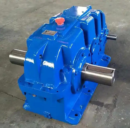
How to adjust the coaxiality between the motor shaft and the input shaft of ZSY180-31.5-1 reducer to meet the acceptance criteria
Adjusting the coaxiality between the motor shaft and the input shaft of ZSY180-31.5-1 reducer should follow a systematic process, combined with high-precision tools and standardized operations, to ensure the acceptance criteria of radial deviation ≤ 0.1mm and angular deviation ≤ 0.5 ° (or ≤ 0.01mm/mm). The following are specific steps and key technical points:
Installation surface treatment
Use a level (accuracy 0.02mm/m) to measure the flatness of the motor and reducer base, with an error of ≤ 0.1mm/m. Use steel shims (0.1-2mm) to level any unevenness, with no more than 3 shims in the shim set.
Clean the flange surface to ensure no oil stains or rust, and avoid false alignment (0.03mm impurities can cause a deviation of 0.05mm).
Tool selection
Basic tools: dial gauge (accuracy 0.01mm), feeler gauge, torque wrench (matched according to bolt specifications, such as M16 bolt torque 80-100N · m).
High precision tool: Laser centering instrument (such as Fixturlaser ECO, accuracy 0.001mm), suitable for heavy-duty reducers such as ZSY180-31.5-1.
2、 Adjust the process in stages
Stage 1: Coarse tuning (preliminary alignment)
Horizontal calibration
Use a spirit level to measure the levelness of the X/Y axis for both the motor and gearbox, and adjust it to ≤ 0.1mm/m using shims.
Visual inspection or straightedge comparison of the flange edges of the two shafts, with radial misalignment controlled within ≤ 0.5mm.
Pre installation of coupling
Priority should be given to using elastic couplings (such as plum blossom shaped), with a permissible radial deviation of ≤ 0.5mm and angular deviation of ≤ 1 °.
Stage 2: Fine tuning (laser alignment instrument)
Equipment installation
The laser emitter is fixed to the motor shaft, and the receiver is fixed to the reducer shaft, with a distance of ≥ 3 times the shaft diameter (≥ 180mm if the shaft diameter is 60mm).
Enter parameters (speed, shaft diameter, coupling type) to enter dynamic centering mode.
Deviation correction
Radial deviation: Adjust the motor foot gasket (gasket thickness=deviation value × 1/2).
Angular deviation, calculate the thickness of the gasket according to the formula:
For example, when the deviation is 0.6mm, the coupling diameter is 100mm, and the foot spacing is 200mm, a 0.15mm gasket needs to be added to the front foot
3、 Acceptance criteria and verification
Allowable deviation range
Rigid connection: radial ≤ 0.1mm, angular ≤ 0.5 ° (or ≤ 0.01mm/mm).
Flexible connection: radial ≤ 0.5mm (elastic coupling can be relaxed to 1mm), angular ≤ 3 °.
Final testing
Use a dial gauge to retest the outer circle and end face of the coupling, rotate the shaft once, and the maximum runout should be ≤ 0.1mm.
The laser alignment instrument displays real-time deviation, and after confirming that both radial and angular directions meet the standards, tighten the bolts.