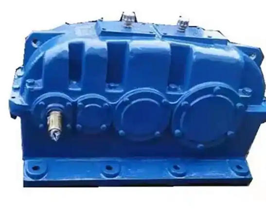
How to ensure the levelness of the motor and gearbox when installing ZSY400-25-I hard toothed gear reducer
When installing ZSY400-25-I reducer (large hard tooth surface cylindrical gear reducer, suitable for high-power motors), ensuring the levelness of the motor and reducer is the core prerequisite for ensuring stable operation of the transmission system, controlling coaxiality, and extending the life of components. The adjustment of levelness should follow the principle of "benchmark first, followed by passive adjustment, rough adjustment first, fine adjustment later, zone measurement before overall verification", combined with the equipment installation form (mainly horizontal) and basic conditions, and achieved through precise measurement and mechanical adjustment. The following is the detailed operation process:
1、 Preparation in advance: Clarify benchmarks, tools, and standards
1. Determine the adjustment benchmark
As a precision transmission core, the ZSY400-25-I reducer requires extremely high internal gear meshing accuracy for installation levelness, and is usually rigidly connected to downstream equipment such as drums and crushers. Therefore
Using the levelness of the gearbox as the 'core benchmark'
The levelness of the motor needs to be adapted to the reducer, rather than vice versa (to avoid damaging the coaxiality between the reducer and downstream equipment).
2. Essential tools and materials
3. Clarify the acceptance criteria for levelness

Strictly follow the ZSY400-25-I reducer technical manual and related standards (such as JB/T 8853-2017 Cylindrical Gear Reducer), with the following core standards:
Levelness of reducer:
The allowable deviation of the longitudinal (along the axis centerline direction) levelness of the fuselage is ≤ 0.03mm/m;
The horizontal tolerance of the fuselage (perpendicular to the axis centerline direction) is ≤ 0.05mm/m.
Motor levelness:
It needs to be "adapted" to the levelness of the reducer, and the "parallelism error" between the motor shaft centerline and the reducer input shaft centerline should be ≤ 0.05mm/m (to avoid coaxiality deviation caused by motor inclination);
The allowable deviation of the longitudinal/transverse levelness of the motor itself is ≤ 0.05mm/m.
Axis levelness:
The allowable deviation of the "radial levelness" (measured at the shaft neck) of the input shaft, output shaft, and motor shaft of the reducer is ≤ 0.02mm/m (indirectly verified by detecting the radial runout when the shaft rotates through a dial gauge).
2、 Core process: Adjust the levelness step by step
Step 1: Basic preprocessing and equipment positioning (prerequisite for leveling adjustment)
1. Basic surface acceptance and treatment
Check the surface of the concrete foundation (or steel structure base) of the reducer and motor: it should be flat, free of oil stains, and without hollowing, with a surface roughness Ra ≤ 12.5 μ m;
Use a spirit level to initially measure the levelness of the foundation surface. If the deviation is too large (>0.5mm/m), use cement mortar to level or polish it. Wait until the foundation is completely cured (concrete curing ≥ 28 days) before installing.

