How to use a spirit level to level the machine base when installing B14-1:87-2.2KW cycloidal pinwheel reducer
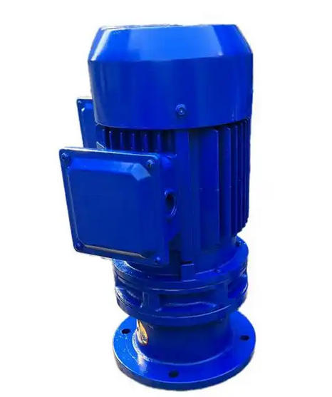
B14 is a flange connected cycloidal pinwheel reducer. The 2.2KW power corresponds to an appropriate size of the base. The core of leveling is to ensure that the output shaft of the reducer is coaxial with the driven equipment shaft, and the base is level without stress, so as to avoid vibration, bearing damage and other problems during operation. The specific steps are as follows:
1. Prepare tools and venue
Choose a frame level or bar level with an accuracy of not less than 0.02mm/m, equipped with a feeler gauge, wrench, jack/adjusting shim (stainless steel or cast iron material is preferred to avoid deformation); Clean the surface of the installation foundation, remove oil stains, burrs, and debris, and ensure that the flatness error of the foundation plane is ≤ 0.1mm/m.
2. Preliminary placement and positioning
Lift the reducer to the designated position on the installation foundation, install the foot bolts but do not tighten them, and reserve 2-3mm adjustment allowance; Ensure that the flange surface of the reducer is facing in the same direction as the driven equipment (such as motors, working machines) to avoid secondary displacement in the future.
3. Level placement and measurement (key steps)
Longitudinal measurement: Place the level along the axis direction of the gearbox output shaft on the machining plane of the machine base (preferably the flat surface or flange end face near the anchor bolt), and observe the position of the level bubble. Which side does the bubble lean towards? This indicates that the side is too high. It is necessary to loosen the corresponding side anchor bolt or add a plug ruler under the shim on the other side to adjust.
Horizontal measurement: Rotate the level by 90 ° and place it on the same set of machining planes along the direction perpendicular to the output axis. Repeat the above measurement and adjustment operations.
Tolerance requirement: The vertical and horizontal levelness error should be controlled within 0.05mm/m, and the qualified standard is that the bubble is centered and stable.
4. Multi point retesting and stress release
Repeat measurements on the corresponding planes of the four anchor bolts on the machine base to avoid single point measurement errors; During the adjustment process, gently tap the side of the reducer base to release installation stress and prevent deformation of the base due to uneven stress. After retesting and passing the test, gradually tighten the anchor bolts diagonally (torque according to the equipment manual, generally 25-40N · m for 2.2KW reducers).