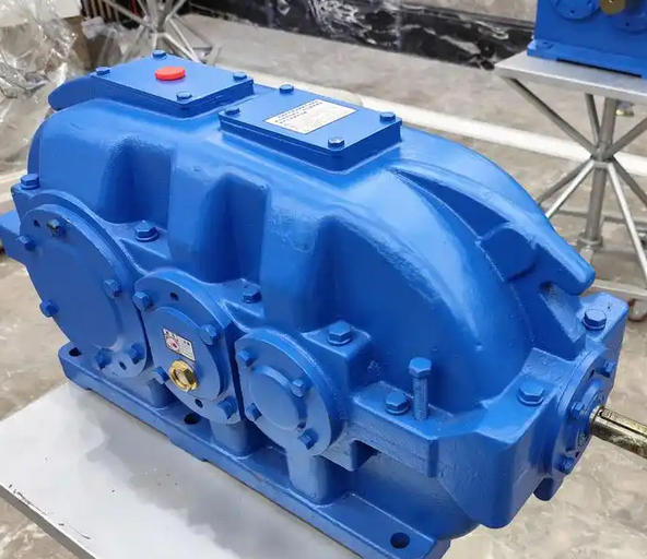
How to detect the system natural frequency of DCY500-18-II reducer
The detection of the natural frequency of the DCY500-18-II reducer system requires a combination of experimental testing and numerical simulation. The specific method is as follows:
1、 Experimental testing method
Hammer method (modal analysis)
Use a force hammer to strike the gearbox housing, collect vibration response signals through an acceleration sensor, and identify the frequency corresponding to the resonance peak after FFT transformation.
Measurement point arrangement: evenly arrange 6-8 measurement points on the surface of the shell (such as near the input/output end and bearing seat), covering X/Y/Z three-way vibration.
Equipment requirements: Acceleration sensors (such as B&K 4382) should be paired with a data acquisition system (sampling frequency ≥ 10kHz).

Exciter method
Apply sweep sine excitation through an electromagnetic shaker, scan the frequency range (e.g. 5-2000Hz), and record the peak points of the amplitude frequency response curve.
2、 Numerical simulation method
Finite Element Modeling
Establish a multi-body contact model that includes gears, bearings, and shells, and calculate modal shapes and natural frequencies.
Key parameters: material elastic modulus, Poisson's ratio, damping coefficient; The gear mesh stiffness is calculated according to ISO 6336 standard.
Verification comparison: The error between finite element results and experimental data should be ≤ 15% (such as an error of 4.5% -16.5% in a certain case).
Boundary condition setting
Simulate actual installation constraints (such as bolt fixation) to avoid rigid modal interference.
3、 Precautions
Test environment: It is necessary to isolate external vibration interference and can be tested under no-load or rated load, but the load may affect higher-order modes.
Frequency range: Focus on 0-5000Hz, and additional testing is required for the dynamic response of mining reducers under impact conditions.

