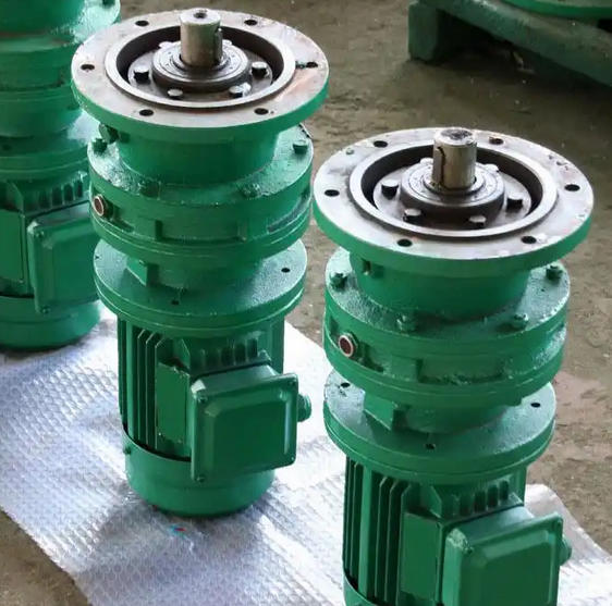
How to prevent cracks in XLD8145-59-2.2KW cycloidal pinwheel reducer
The cracks in the XLD8145-59-2.2KW cycloidal pinwheel reducer are mainly caused by material and process defects during manufacturing, installation deviations, as well as abnormal loads, temperatures, and lubrication during operation. Preventive measures can be taken throughout the entire process of manufacturing, installation, operation, and maintenance, as follows:
Control the manufacturing and processing processes to reduce potential hazards from the source
Optimize materials and heat treatment processes: Key components such as the gearbox housing and cycloid gear should be made of high-strength materials that meet standards. For example, the cycloid gear should be made of 20CrMnTi alloy steel and undergo standardized carburizing and quenching treatment to ensure a surface hardness of HRC58-62. The depth of the hardened layer should be controlled at 0.8-1.2mm to avoid cracks caused by insufficient material toughness and low fatigue strength. Simultaneously using vacuum low-pressure casting technology to produce shell blanks, the porosity is controlled below 0.3% to prevent defects such as slag inclusion and porosity during casting from becoming the source of cracks.
Optimize structure and processing details: For stress concentration prone areas such as shoulder transitions and keyway roots, ensure sufficient fillet size during processing, such as keyway root fillet R not less than 0.5mm, to reduce stress concentration factors. In addition, control the surface roughness of the processed material to avoid problems such as rough cutting marks. For example, the tooth surface roughness Ra should be lower than 1.6 μ m to prevent the formation of crack initiation points on rough surfaces.
Standardize installation and assembly processes to avoid additional stress damage
Ensure installation accuracy: Level the foundation platform before installation to ensure that the horizontal error does not exceed 0.2mm/m; Calibrate the coaxiality of the motor and reducer with a laser centering instrument to ensure that the axis deviation is ≤ 0.05mm and avoid generating additional bending moments during operation. When installing bearings, use a hydraulic press to control the interference fit to prevent micro cracks on the shaft surface caused by tight interference fit. At the same time, adjust the axial clearance of the bearings to a reasonable range to ensure smooth operation.

Control the tightness of the connection: The torque angle control method is used to install the connecting bolts, ensuring that the pre tightening force deviation of the bolts is less than 5%, to avoid micro motion wear of the joint surface caused by insufficient or uneven pre tightening force, which may lead to flange surface cracks. Check all connection parts after installation to eliminate any potential looseness hazards.
Scientific operation and maintenance, delaying the occurrence of fatigue cracks
Avoid abnormal load: The rated power of this model of reducer is 2.2KW. It is strictly prohibited to operate beyond the nameplate load during operation. A torque limiter can be installed to control the impact load within 1.5 times the rated value. At the same time, reduce frequent starting and stopping, and it is recommended to start and stop no more than 10 times a day to reduce the cumulative damage of components caused by alternating stress.

