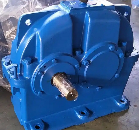
How to solve the problem of insufficient assembly accuracy of ZDY355-3.15-1 hard tooth surface gear reducer
To solve the problem of poor assembly accuracy of ZDY355-3.15-1 hard tooth surface gear reducer, the following aspects can be taken into account:
Precision control of parts processing
Box processing: The assembly reference surface of the box should have high flatness and small surface roughness. When processing, first process a larger plane as the positioning base for hole processing, and select the two holes with longer hole distances and the lower plane of the opening and closing surface as the rough reference. After precision machining, scrape and grind the opening and closing surfaces of the box body and lid to ensure that the joint surface gap is not 0.03mm. The deformation of the boring bar under stress will affect the accuracy of the hole system. The box clamping should be placed as close as possible to the boring machine column to reduce the overhang of the boring bar. The machining of bearing holes adopts a rough boring semi precision boring precision boring process route, and when the coaxial hole span is large, a guide sleeve mold can be used.

Gear machining: Select the appropriate manufacturing accuracy level based on the gear usage conditions and precision requirements, and use advanced machining equipment and processes such as CNC gear hobbing machines, gear grinding machines, etc. At the same time, advanced surface treatment techniques such as carburizing and nitriding are used to improve the hardness and wear resistance of gears. After processing, gear measurement centers and other equipment are used to test the accuracy of gears, ensuring that tooth profile errors, tooth pitch errors, etc. meet the requirements.
Assembly process control
Component cleaning: Key mating surfaces are cleaned using kerosene ultrasonic waves to ensure that there are no metal debris residues on gear meshing surfaces, bearing installation surfaces, etc., preventing impurities from affecting assembly accuracy and component wear.
Bearing assembly: For bearings with interference fit, the hot fitting method can be used to control the oil bath heating temperature at 120 ± 5 ℃, and the insulation time is calculated based on 1.5 minutes per millimeter of the bearing inner diameter. When assembling, pay attention to the installation direction of the bearings to avoid reverse installation. For angular contact bearing groups, a spring load cell is used to measure the preload torque, which is generally 0.03-0.05 times the rated dynamic load of the bearing to ensure that the bearing has appropriate preload force.
Gear assembly: Use red lead powder to detect gear meshing spots, requiring a contact rate of ≥ 45% along the tooth height direction and ≥ 60% along the tooth length direction. Adjust the gear backlash through the shim group to ensure that the normal backlash value meets the ISO1328 standard. For example, when the modulus is 3-6mm, it is recommended to use 0.08-0.15mm. During assembly, attention should also be paid to the axial positioning of the gear to prevent it from moving in the axial direction.
Coaxiality adjustment: When installing the coupling, use tools such as a dial gauge to measure and adjust the coaxiality between the reducer, motor, and working machine shaft. Generally, the coaxiality error should not exceed 0.05-0.1mm. By adjusting the position of the motor or working machine, the radial and axial runout of the shaft at both ends of the coupling can be minimized.

