The specific process for verifying the durability of the DCYK200-40-1 gear reducer involves several steps. First, the gear reducer undergoes a series of tests under various operating conditions to sim
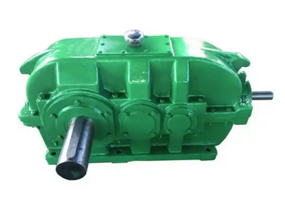
The durability verification of DCYK200-40-1 gear reducer can refer to the following specific process:
1. Preliminary preparation:
Parameter and file confirmation: Confirm that the reducer model, speed ratio, rated torque, and other parameters are consistent with the design requirements. Check the integrity of the gear material hardness report, bearing accuracy certificate, and other documents, with a focus on verifying whether the depth of the carburized layer on the tooth surface meets the HRC58-62 standard.
Equipment calibration: The torque sensor needs to undergo regular static calibration, with an error controlled within ± 0.3%. The sampling rate of each channel in the temperature acquisition system should not be less than 100Hz, and the frequency response range of the vibration measuring instrument should cover 0-10kHz. All measuring equipment must hold a valid third-party calibration certificate.
Environmental setting: The testing laboratory needs to maintain an environmental standard of temperature (25 ± 3) ℃ and humidity ≤ 60% RH. If there are special operating condition simulation tests, a programmable temperature control system should be equipped to achieve wide range temperature simulation capability from -40 ℃ to 120 ℃.
2. No load operation test:
Start up current monitoring: Record the instantaneous peak current during the start-up phase, and the normal value should not exceed 1.5 times the rated current.
Temperature rise detection: After continuous operation for 2 hours, detect the temperature rise of the bearing position. A temperature rise of ≤ 35K is considered qualified.
Axial radial runout detection: Use a laser alignment instrument to detect the radial runout of the input/output shaft, with a tolerance of ≤ 0.02mm/m.
3. Load characteristic test: Using a multi-stage loading method, operate at 25%, 50%, 75%, 100%, and 120% rated torque respectively:
Efficiency curve drawing: The rated point efficiency is required to be ≥ 94% (planetary reducer) or ≥ 92% (worm gear reducer).
Backclearance measurement: The axial clearance of precision servo reducers should be ≤ 1arcmin.
Vibration velocity measurement: Record the effective value of vibration velocity at each load point, which should comply with ISO10816-3 standard.
4. Durability verification:
Continuous operation test: Run at full load for 2000 hours, monitor the wear of the tooth surface every 24 hours.
Start stop cycle test: Simulate 50 start stop cycles per day, accumulate 5000 cycles, and check the gear contact spots.
Overload impact test: Apply 150% rated torque impact load and repeat 100 times to test the structural integrity.
Stress wave monitoring: Sensors with a frequency range of 50kHz-1MHz can be used to capture the stress waves generated during gear meshing, in order to detect potential faults in advance.
Lubricating oil testing: Regularly extract lubricating oil samples and use an iron spectrometer to detect the morphology and size distribution of abrasive particles. When layered abrasive particles>15 μ m are found, it indicates that the gear has entered the abnormal wear stage.