Structural Design and Principle of WS120-60-II Worm Gear Reducer
The following is a comprehensive analysis of the structural design and principle of WS120-60-II worm gear reducer:
1. Basic structure and transmission principle
The WS120-60-II reducer adopts worm gear transmission, and its core structure includes:
Worm: As an active component, it is usually designed with single or multiple helical teeth and made of quenched steel (such as 20CrMnTi) to improve wear resistance.
Worm gear: a driven component that meshes with the worm gear, made of cast tin bronze (such as ZCuSn10P1), with the number of teeth determined by the transmission ratio design.
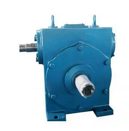
Box body: Adopting an integral structure, it provides support and sealing functions, and some models support horizontal or vertical installation.
Its working principle is based on the meshing of the helical teeth of the worm gear with the tooth surface of the worm wheel, and power transmission is achieved through sliding friction. The input shaft and output shaft are staggered at a 90 ° angle, and the transmission ratio range is usually 10:1 to 60:1.
2. Design Features
Reduction ratio allocation: The two-stage worm gear design (such as WS120-60-II) is connected in series through two-stage transmission, and the total reduction ratio is the product of single-stage reduction ratios (such as 60 × 60=3600), suitable for high torque and low-speed scenarios.
Self locking function: The worm lead angle design enables it to have reverse self-locking ability, which can prevent load reversal.
Heat dissipation optimization: The enclosure may be equipped with heat sinks or forced lubrication systems to address temperature rise issues caused by low efficiency in multi-stage transmission (about 50% -75% for dual stage).